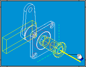
You can perform the steps described below by opening MOVPRT1.ASM located in the Solid Edge Training folder.
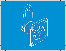
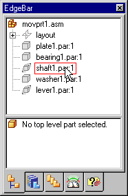
Click the PathFinder tab.
Notice that SHAFT1.PAR is not fully positioned. You can only move parts that are grounded or not fully positioned. If a part is fully positioned, you can use the Suppress command on the shortcut menu to temporarily suppress a relationship.
Choose Home tab→Modify group→Drag Component  . You can move a part along a selected axis, rotate a part around an axis, or move a part in free space.
On the Drag Component command bar, in the Motion analysis list, set the No Analysis option.
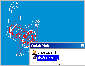
In the application window, use QuickPick to select SHAFT1.PAR. On the Drag Component command bar, set the Move option.
In the application window, position your cursor over the axis shown in the following illustration.
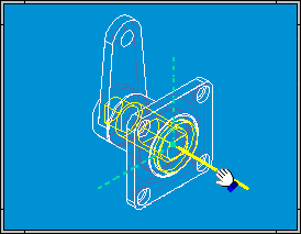
When the axis highlights, press and hold the left mouse button down, then drag your cursor as shown in the following illustration.
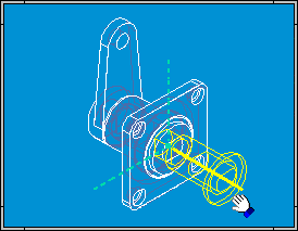
On the Drag Component command bar, set the Rotate option.

In the application window, position your cursor over the axis shown in the following illustration.
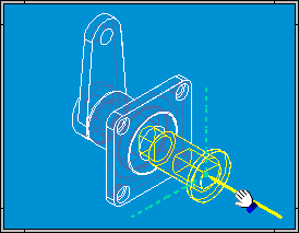
When the axis highlights, press and hold the left mouse button down, then drag your cursor as shown in the following illustration. Notice that LEVER1.PAR also highlights, and rotates with the shaft. The lever rotates because the relationships that control its position allow it to rotate, but not move.
