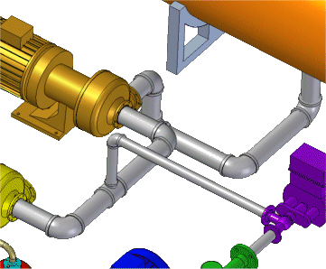
You can use XpresRoute to create a piping route that includes pipes and pipe fittings.

Solid Edge delivers a free complement of pipe fittings to help increase your design productivity. You can increase productivity even more by adding your own parts to the library.
Use the PathXpres command to automatically create a 3D path for the pipe.
To learn how, see Create a path segment with PathXpres.
Use the Line Segment or Arc Segment command to manually draw the path for the pipe.
To learn how, see Create a path segment.
Use the Piping Route command to assign pipe attributes and fittings to a path segment that defines the route the pipe should follow.
You can place pipes and fittings located in a standard parts library or another location outside the library.
Note:
Before placing a part from outside a standard parts library, you must run the PreparePipingComponents.exe utility located in the Solid Edge ST3\Program\Piping Route\Piping Utility folder to create the appropriate coordinate systems and variables for the part file you want to place.
To learn how, see Create a piping route.
Modify the fittings and pipe attributes in an existing piping route
To learn how, see Edit pipes and fittings.
Include additional fittings and pipes to an existing pipe group.
Retrieve or display information for the pipes and fittings.
To learn how, see Create a piping report.