Applies a gear relationship between two parts in an assembly. You use a gear relationship to define how one part will move relative to another part.
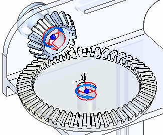
This is useful when working with assemblies that contain gears, pulleys, parts that travel in grooves or slots, and hydraulic or pneumatic actuators.
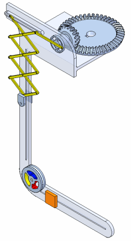
Note:
A gear relationship does not physically position the parts in the assembly. You must use other assembly relationships such as mate, align, and axial align to position the parts.
You can use the command bar to define the type of gear relationship, the movement direction, and a movement ratio that specifies how much one part moves relative to the movement of another part.
You can define the following types of gear relationships:
Rotation-Rotation
Rotation-Linear
Linear-Linear
The basic steps for defining a gear relationship are:
Specify the type of movement you want.
Select the elements.
Define the movement direction.
Define the ratio.
The Gear Type list on the command bar allows you to define the type of movement you want. You can specify whether you want the movement type to be Rotation-Rotation, Rotation-Linear, or Linear-Linear.
Depending on the gear type you specify, you can select faces, edges, or cylindrical axes to define the relationship. For example, to define a Rotation-Rotation gear relationship, you can select cylindrical faces, conical faces, circular edges, or cylindrical axes on the two parts for which you want to control movement.
When you select the elements, a default movement direction is applied. The default movement direction is displayed in the graphic window. You can use the Flip button on the command bar to flip the direction.
The Value 1 and Value 2 boxes on the command bar allow you to define the movement ratio you want. For example, when defining a Rotation-Rotation gear relationship, you may want Part 2 to rotate two revolutions for each one revolution of Part 1.
When defining a Rotation-Rotation gear relationship you can use the Teeth/Turns list to specify whether you want the ratio to be based on the number of teeth or number of revolutions. This can be useful when working with gears, where the number of teeth is known for each gear in a gear set. The Teeth/Turns list is not available when defining a Rotation-Linear or Linear-Linear gear relationship.
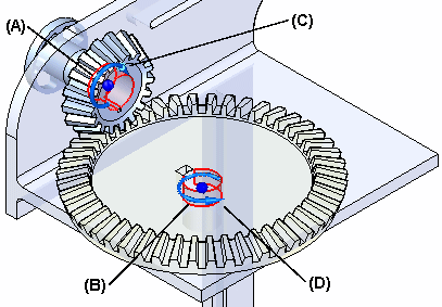
A rotation-rotation gear relationship is useful when defining movement between two gears or two pulleys. This example illustrates using cylindrical faces on two parts (A) and (B) to define the relationship. Notice the symbols which indicate movement direction (C) and (D). You can use the Flip button on the command bar to change the movement direction. In this example, the Teeth/Turns option on the command bar was set to Teeth, and the number of teeth for each gear is used to specify the ratio values.
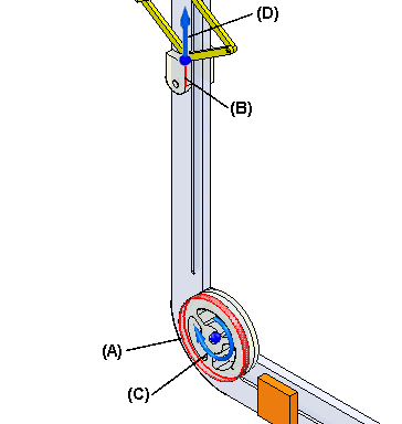
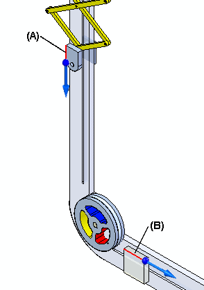
A rotation-linear gear relationship is useful when defining movement between a pulley and a part you want to slide in a groove or slot. This example illustrates using a cylindrical face on a pulley (A) and a linear edge on a part (B) that slides in a slot. Notice the symbols which indicate rotational (C) and linear (D) movement direction. In this example, you specify the linear distance part (B) travels when part (A) rotates one turn. The linear distance you specify is equal to the circumference of the appropriate cylindrical face on the pulley part.
A linear-linear gear relationship is useful when defining movement between two parts you want to slide in grooves or slots. This example illustrates a linear edge on part (A) and a linear edge on part (B) that slide in slots. In this example, you specify the linear distance part (A) and (B) travel.
You can also use the linear-linear option when specifying movement that occurs between two hydraulic or pneumatic actuators. If the actuators have different internal diameters, you can define an appropriate ratio using the Value 1 and Value 2 boxes on the command bar.
You can use other commands in Solid Edge to see how the assembly reacts to the relationships you applied. To allow movement, the proper parts must be under-constrained or have assembly relationships suppressed in the axes in which you want to observe movement. If all the parts in the assembly are fully constrained, no movement is possible.
You can use the Motor command to select a part in the assembly and define motor characteristics such as motor type (rotational or linear), motor direction, the rate at which the motor will move, and so forth.
Using the previous example, you can specify a rotational motor on the large gear part using the Motor command, and specify the rotational axis shown in the following illustration. With the gear relationships outlined above, you can then observe the movement using the Simulate Motor command. For more information, see the Motor command and Simulate Motor command Help topics.
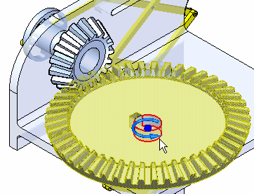
You can use the Move Part command to move a part in the assembly and observe how the other parts react to the movement. Using the previous example, you can select the large gear part, specify a movement type of Rotational on the Move Part command bar, and then specify the rotational axis shown. For more information, see the Move Part command Help topic.