Use the Maintain Alignment Set command ![]() while initially placing or modifying linear dimensions to simultaneously align dimensions and create alignment sets.
while initially placing or modifying linear dimensions to simultaneously align dimensions and create alignment sets.
Maintain Alignment Set can be turned on or off in the Dimensions group on the ribbon. There is no associated command bar.
Note:
The default state of Maintain Alignment Set is on.
If you turn Maintain Alignment Set off, it will stay off until you turn it on again. This setting is a user preference in all environments with the exception of Draft. Draft has its own user preference for this command.
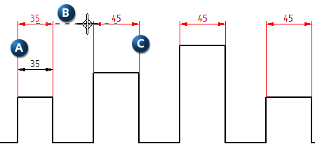
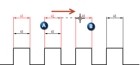
When you turn Maintain Alignment Set on and initially place an alignment set, a dimension (A) can be aligned (B) with another dimension of the same type (C). An alignment set consisting of dimensions A and C is created in the process.
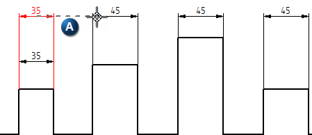
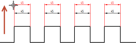
When you turn Maintain Alignment Sets off, dimensions can be aligned (chained or stacked) with existing dimensions by using alignment indicators (A). However, because the command is off, the dimensions are not added to an alignment set or create an alignment set.
Note:
If Maintain Alignment Set is turned off, it does not affect existing alignment sets.
Linear dimensions can be aligned during initial placement or modification by using alignment indicators. The on or off state of Maintain Alignment Set has no affect on this; alignment indicators always display.
Alignment indicators display as dashed lines to show horizontal or vertical alignment while you create or modify dimensions. Alignment indicators work similarly to IntelliSketch relationship indicators. If you click when a horizontal or vertical indicator line is displayed, the element you are drawing or modifying will be horizontally or vertically aligned with the element the indicator line leads to.
When creating or modifying dimensions, alignment indicators use the position of the dimension values along the dimension lines as the basis for alignment.
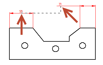
As you position a linear dimension (A), you can move over another dimension (B) to display the dashed alignment indicator (C). When you click the mouse button, the first dimension snaps into collinear alignment with the second. 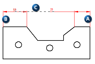
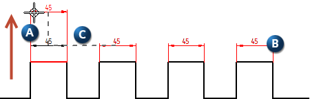
Dimensions can be stacked using alignment indicators. For stacked dimensions, a perpendicular dashed line (A) is attached to the parallel dashed line (B). The perpendicular line ascends or descends, based on positioning preference, and is attached to the dimension being created or modified (C). The distance between stacked dimensions is set by the stack pitch which is a ratio of the dimension text size. The stack pitch can be modified in the Lines and Coordinates tab in the Dimension Properties dialog box or the Dimension Style dialog box.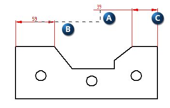
Note:
You can use the Smart Dimension and Distance Between commands at the same time when aligning dimensions and creating alignment sets. Maintain Alignment Sets must be turned on for dimensions to be added to alignment sets.
Associative chain and stack groups created by the Distance Between command previous versions are converted to alignment sets.
A dimension can be added to an existing alignment set while the dimension is being actively modified. However, the dimension being modified and the alignment set must be the same type. Parallel dimensions can be added to an alignment set with other parallel dimensions. An angular dimension with a specific angle can be added to an alignment set with angular dimensions sharing that specific angle. An angular dimension with a different angle cannot be added to that group.
Moving an alignment set
Dragging any member dimension of an alignment set moves the entire group.
Moving a single dimension while keeping the alignment set intact
Press the Alt key while dragging a single dimension (A) in an alignment set (B) to move only that dimension. Stack distances (C) are indicated during this process.
Merging Alignment Sets
Drag any member dimension from one alignment set (A) to another alignment set (B) to merge the two.
Note:
Dimensions in the alignment set flip automatically when the entire set is moved from above the drawing to below or from below to above. The dimension being dragged will not flip, but the other dimensions in the group will flip at different points.
Deleting a member dimension in an alignment set simply removes the dimension from that group. The alignment set is not split.
Arrange dimensions automatically in a drawing
Break Alignment Set
Split Alignment Set
Remove from Alignment Set
Arrange Dimensions
Arrange Dimensions command bar