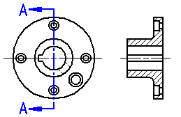
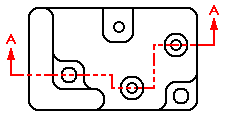
Cutting planes are used to create section views. The Cutting Plane command draws a cutting plane line on the part view you want to use as the basis for the section view.

Cutting planes can be used just once.
You can draw the cutting plane on any part view. This can be any orthographic, auxiliary, or detail view on the drawing.
Auxiliary views often show the part at the optimal orientation for making the section cut.
A detail view can be useful for creating sections due to its scale. Sections created from detail views inherit the same scale as the detail view.
You draw a cutting plane using many of the drawing tools. When you select the Cutting Plane button and then select a part view, the command ribbon updates and displays commands for drawing a cutting plane.
A cutting plane can consist of a single line or multiple elements, such as lines and arcs.

If you draw a cutting plane that consists of more than one element, the cutting plane must meet the following requirements:
The elements must meet at their end points.
The elements cannot form a closed region or have loops.
The elements cannot cross each other.
Any arcs in the cutting plane cannot be the first or last element.
Any arcs must be connected to a line at both ends of the arc.
If you draw a cutting plane on a detail view so that it extends beyond the cropping boundary, then the geometry outside the detail view, to the extent of the cutting plane, will be included in the section view. If you draw the cutting plane so that it is completely contained within the detail view, then only that geometry will be included in the section view.
When you have finished drawing the cutting plane, you select the Close button on the Home tab. You can then dynamically define the cutting plane view direction by clicking on one side of the view to be sectioned. If you need to change the view direction, you can use the cursor to drag the cutting plane view direction lines to the opposite side of the cutting plane.
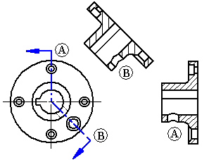
If the cutting plane is defined by multiple lines that are not orthogonal, or the first and last lines in the cutting plane are not parallel, you must specify whether the first line (A) or last line (B) in the cutting plane will be used to define the fold angle for the section view rotation. The line you select affects the placement angle of the section view.

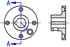
You can include arcs in cutting planes. If an arc is included in the cutting plane, it must be connected to a line at both ends. You cannot begin or end a cutting plane with an arc.
When you create a section view from a cutting plane that includes an arc, the Revolved Section View option on the command bar is automatically selected. You can clear this option if you want to create a non-revolved section view.

Note:
You cannot create additional section views from a section view that was generated from a cutting plane that includes an arc.
After a cutting plane is created, you can control the display of cutting plane lines by selecting the cutting plane annotation and then using the options on the Cutting Plane Selection command bar and in the Cutting Plane Properties dialog box.
After a section view is placed, you can control the display of the cutting plane graphics using the following check box on the General tab (Drawing View Properties dialog box):
Show view annotation (Cutting Plane, Detail Envelope, Viewing Plane)
You also can hide the cutting plane by moving the cutting plane element to its own layer, and then hiding the layer. To learn how to do this, see the Help topic, Hide a cutting plane.
You can control the display of edges resulting from cutting plane lines created with multiple line segments using the Advanced Edge Display Options dialog box or in the Drawing View Properties dialog box. To learn how, see Show or hide cutting plane lines in section views.
You can add dimensions and relationships between the cutting plane and the part view to control the position, size, and orientation of the cutting plane.
You can edit the shape of the cutting plane line by double-clicking it or using the Edit button on the Cutting Plane Selection command bar.
You can lengthen or shorten the open end of a terminator on the view direction line by selecting the end of the terminator that is not connected to the cutting plane, and then dragging it.
You can select and move the cutting plane caption text.
You can modify formatting attributes of a selected cutting plane annotation by editing its properties.
The default content and appearance of cutting plane lines, terminators, and captions is defined in the Drawing View style that is applied to the view.
For example, you can:
Lines and arrows
Define the type and size of cutting plane lines and arrows on the Lines tab in the Drawing View Style dialog box. There, you can specify whether the cutting plane arrows point toward or away from the cutting plane, as well as the offset between the arrow and the line.
Text location
Define where the cutting plane caption text is placed with respect to the cutting plane lines using the Cutting plane caption location list on the Caption Format tab in the Drawing View Style dialog box.
Example:
The Direction Line Open End option positions the cutting plane caption text at the open end of the cutting plane.
If your cutting plane terminator option is set to Point Away, the text is positioned as shown at (A).
If your cutting plane terminator option is set to Point Toward, the text is positioned as shown in (B).

Cutting plane label text
Define the alphanumeric label text that appears in the caption of a cutting plane using the Specify Annotation Letters dialog box. You can open this dialog box from the Annotation tab in the Solid Edge Options dialog box.
For more information, see Assigning view annotation labels.
For more information, see the following Help topics: