Solid Edge can manage large, complex assemblies containing many parts and subassemblies. The Assembly environment contains commands for fitting parts together with natural assembly techniques such as mate and align. Solid Edge accommodates the fact that most parts are designed in the context of an assembly. To support this workflow, Solid Edge provides tight integration with the part modeling environments , visualization tools, data management tools, and part-to-part relationship management tools. Solid Edge makes it easy to manage assembly data from the earliest phases of project planning, through revision cycles, manufacturing, project maintenance, and archival.
The 2D assembly sketching capability in the Solid Edge Assembly environment supports assembly-focused design. This capability allows you to sketch 2D elements in the assembly document. You can include assembly sketch geometry to construct or edit 3D parts.
The Assembly environment allows you to create assembly relationships between parts. These relationships are automatically maintained throughout the development of the design to preserve your design intent. For example, when you mate two part faces, they remain mated when either part is modified. Solid Edge automatically maintains these relationships throughout the development of the design.
The Pathfinder tab makes working in an assembly view easy. PathFinder is a tool that helps you navigate assembly models. PathFinder contains text and symbolic representations of the components of an assembly, and the relationships between components, in an outline format. You can use PathFinder to find and activate the parts and relationships that make up the assembly, and to control their display. PathFinder gives designers and engineers an uncluttered view of assemblies and provides tools for working with assemblies more efficiently. It is also useful for project managers whose primary involvement with assemblies is administrative.
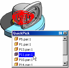
QuickPick is a unique selection tool that makes it easy to locate parts and subassemblies within complex assemblies. When you move the cursor over an area dense with parts, the cursor displays a prompt (A) to let you know that QuickPick is available.

By clicking the mouse button indicated on the QuickPick prompt, you can display a dynamic list with an entry for each part in the vicinity of the cursor. Passing the cursor over the entries highlights each related part--even parts that are not visible in the view. Clicking an entry selects the related part.

Solid Edge provides interference analysis to verify whether space is occupied by more than one solid. If interference is detected, you can use one of several methods to analyze the results, such as creating an ASCII report file, displaying the interfering volumes, and highlighting parts that interfere with each other.
Solid Edge offers a robust set of functions for managing documents throughout a project life cycle. Document properties provide for easy tracking and maintenance. You can save documents in alternate formats and import documents from other systems. You can easily create parts lists, exploded bills of materials, and other types of reports. Document routing and status settings allow for revision control throughout the review and approval cycle.
Solid Edge enables you to create exploded views while maintaining your assembly structure and part-to-part relationships. You can have the system automatically explode an assembly in a defined direction and then manually move and position parts as needed.