A contextual model editing tool called Command bar increases productivity by making operations available based on what is currently selected. Command bar always displays a default command, but it also provides access to other operations that you might want to perform on the selected geometry.
For example, if you select a rectangular region bounded by lines in a part document, then command bar makes the Extrude command the default action and displays the options for creating either a protrusion or a cutout. It also provides drop-button menu access to alternative actions, such as creating a revolved protrusion.
If you select additional geometry or remove geometry from the selection set, then command bar responds with a new or updated list of options.
Command bar also displays when you select a command, such as Hole, Round, or Thin Wall, rather than geometry. The options it displays vary with the command.
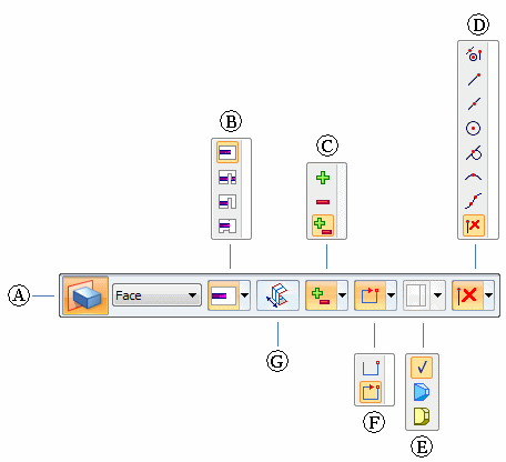
This example illustrates the comprehensive set of extrusion options that are available on command bar when you select a sketch region.
|
Extrude Command bar |
|
|
(A) |
Action menu |
|
(B) |
Extent type |
|
(C) |
Add/Cut mode |
|
(D) |
Keypoints selection |
|
(E) |
Treatments |
|
(F) |
Sketch region type |
|
(G) |
Symmetric extent |
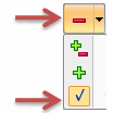
Note:
When you open a list on command bar, notice that the default or current selection for that option is indicated by a highlighted check mark, rather than the corresponding icon. For example:
To learn more about these options, see the Help topic, Extrude command bar.