 Coincident Plane command (ordered)
 Coincident Plane command (ordered)
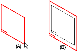
Creates a new reference plane that is coincident with a selected part face or an existing reference plane. When you create a new reference plane based on an existing reference plane (A), the x-axis orientation of the new reference plane (B) matches the x-axis orientation of the existing reference plane.
While you are creating a new reference plane based on a part face (A), the x-axis orientation (B) of the new reference plane is automatically defined using a linear edge (C) on the part face.

If the face you select does not have any linear edges, the x-axis orientation of the new reference plane is defined using one of the default reference planes (A).

When you create a new reference plane using a part face, you can define a different x-axis orientation using the following hot keys:
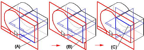
An upper or lower case N to rotate counterclockwise to the next linear edge (A), (B), (C):
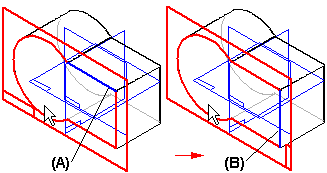
An upper or lower case B to go back to the previous linear edge (A), (B):
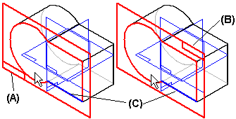
An upper or lower case T to toggle the x-axis orientation (A), (B) to the opposite end of the current linear edge (C):
An upper or lower case P to use a base reference plane that intersects with the reference plane you are defining. When you press the P key, the software automatically selects one of the intersecting base reference planes (A). If you want to use a different base reference plane, press the P key again (B). An advantage to this approach is that the x-axis orientation remains constant. (The P option is not available in the assembly environment.)
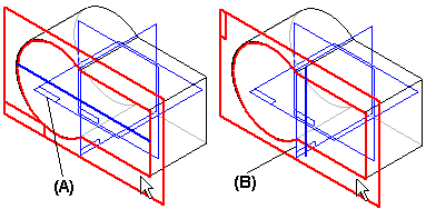
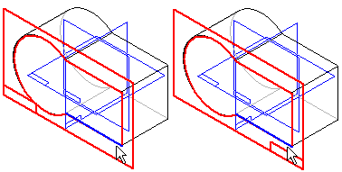
An upper or lower case F to flip the normal direction of the reference plane, which changes the x-axis orientation.
Note:
When you run this command from the References group, it creates a global reference plane. When you run it from a command bar, it creates a local reference plane for the current feature.