 Coincident Plane command (synchronous)
 Coincident Plane command (synchronous)
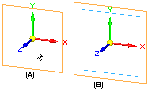
Creates a new reference plane that is coincident with a selected part face or an existing reference plane. When you create a new reference plane based on an existing reference plane (A), the x-axis orientation of the new reference plane (B) matches the x-axis orientation of the existing reference plane.
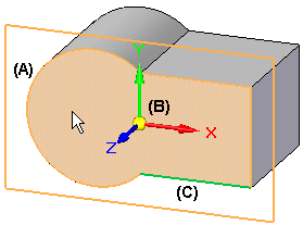
When you create a new reference plane based on a planar face (A), a temporary x-axis orientation (B) for the new reference plane is automatically defined using a linear edge on the face (C). You can accept the x-axis orientation that is automatically assigned, or you can define a new x-axis orientation using hot keys.
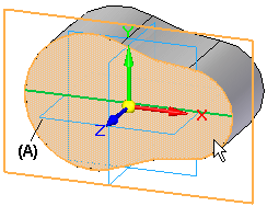
If the face you select does not have any linear edges, the x-axis orientation of the new reference plane is defined using one of the default reference planes (A).
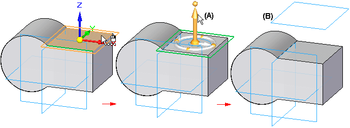
After the new coincident reference plane is created, the steering wheel (A) is displayed on the new reference plane, in case you want to move the reference plane to a new location. For example, you may want to move the reference plane to be parallel and offset from (B) the existing plane or face.
When you create a new reference plane using a part face, you can define a different x-axis orientation using the following hot keys:
An upper or lower case N to rotate counterclockwise to the next linear edge (A), (B):
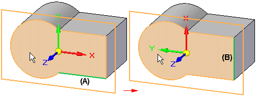
An upper or lower case B to go back to the previous linear edge (A), (B):
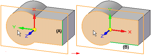
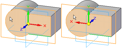
An upper or lower case T to toggle the x-axis orientation (A), (B) to the opposite end of the current linear edge (C):
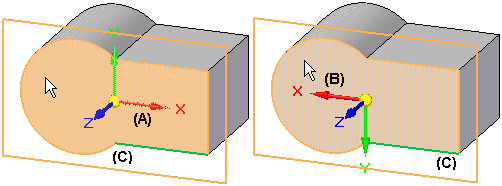
An upper or lower case P to use a base reference plane that intersects with the reference plane you are defining. When you press the P key, the software automatically selects one of the intersecting base reference planes (A). If you want to use a different base reference plane, press the P key again (B). (The P option is not available in the assembly environment.)
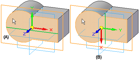
An upper or lower case F to flip the normal direction of the reference plane, which changes the x-axis orientation.
The command bar is available only in the Assembly environment.