Connect relationships are useful when you cannot position a part using a mate or planar align relationship. You can also use a connect relationship to position a part with respect to an element that is in a part, subassembly, or top-level assembly sketch.
You can specify a positive or negative offset value with a connect relationship.
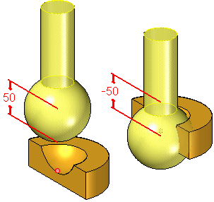
When two parts in an assembly cannot be positioned properly by mate and align relationships, you can position them using connect relationships. A connect relationship positions a keypoint on one part with a keypoint, line, or face on another part. For example, you can apply a connect relationship to position the center of a spherical face on one part with respect to a spherical face on another part.
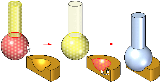
You can use the following methods to apply connect relationships:
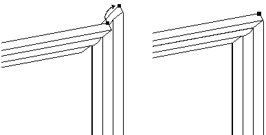
Point-to-Point: In the following figure, a mate relationship is applied between the mitered corners of the parts. A connect relationship, which ties a point on one part to the appropriate point on another, connects the two corners properly. A floating align relationship between the back surfaces fully positions the part.
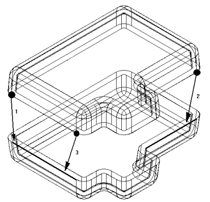
Point-to-Line: In the following example, a mate relationship is applied between the faces of the two parts. Because the sides of each part are drafted, there are no part faces which you can use to apply a planar align relationship. You can apply three connect relationships between the keypoints on the top part and the linear edges on the bottom part.
Point-to-Plane: In the following example, the lower right pin is positioned to a depth that just touches the surface of a reference plane.
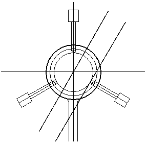
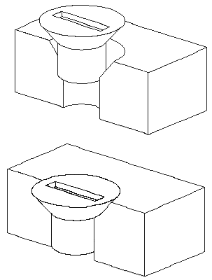
Cone-to-Cone: In the following example, the cone on the fastener is connected to the cone on the countersunk hole on the plate. When you add a connect relationship between two conical faces, the keypoint that represents the theoretical intersection of the individual cones are connected. You can also apply an offset value to a connect relationship between two conical faces.
End points of lines, arcs, and ellipses
Midpoint of a line (edge centerline)
Arc center point
Circle center point
Elliptical element center point
Spherical surface center point
Conical surface center point
Linear edges (including tangent edges)
Reference axis
Axis of a cone, torus , spun surfaces and a sphere.
Planar part surfaces
Reference planes
Faces of a torus, cone or sphere.
Connect a point on the first part to a point on the second part
Connect a point on the first part to a line on the second part
Connect a point on the first part to a face on the second part
Connect a line on the first part to a point on the second part
Connect a face on the first part to a point on the second part
Note:
You can also use an axial align or a connect relationship to position a part with respect to a keypoint or a line in an assembly sketch.