You can open .stl ASCII or Binary documents in Solid Edge assembly, part, or sheet metal with the Open command. On the Open File dialog box, after you select the .stl document you want to open, click the Options button to display the STL Import Options dialog box. Since .stl documents are unit-less, use this dialog box to specify the units for the document.
Note:
A .stl document contains only information about facet bodies. If you open a .stl document containing multiple bodies in an assembly template, Solid Edge translates the multiple bodies into a single part document with a single entry in Feature PathFinder.
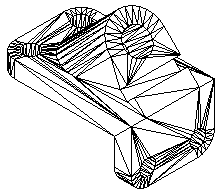
.Stl documents contain facet bodies. A facet body is a surface representation defined by triangles.

When you import a .stl facet body, it is stored in Solid Edge as a non-Parasolid body. The facet body is displayed in Feature PathFinder as a part copy. However, since the facet part copy is a non-Parasolid body, the rules are different than those for a normal part copy.
When you import a facet body, it can be placed as a construction or as a base feature. To place the facet body as a base feature, select the Make Base Feature option on the STL Import Options dialog box. Even placed as a base feature, it is not considered a design body since no material can be added or removed from this type of feature.
When you import a facet body, all faces are merged into a single part copy and represented by a single entry in Feature PathFinder.
You cannot modify a facet part copy.
The Insert Part Copy command does not support .stl documents.
You cannot locate faces, edges, or vertices of a faceted body. You can only locate the entire body.
Commands that require faces, edges, or vertices as input will simply fail when trying to locate the faces, vertices or edges of a faceted body. For example, when drawing a sketch, the Sketch command will not locate faces, edge, and vertices of a faceted body. When the Solid Edge part file contains a facet body, any commands that only add or removes material from the base feature are disabled.
Commands that calculate physical properties are supported for facet bodies in a Solid Edge part document.
You can check for interference between facet bodies in a Solid Edge assembly document.
Faceted bodies are represented in Feature PathFinder with a unique icon and name. You can control the display mode of the facet body in Solid Edge, as with any other design bodies. However, when the body is shaded, the edge display is never enabled. You can use the shortcut menu in either Feature PathFinder or the graphics window to show or hide the facet body.
You can save Solid Edge Assembly, Part and Sheet Metal documents in .STL format with the Save As command. On the Save As dialog box, after you select the Solid Edge document you want to save, click the Options button to display the STL Export Options dialog box. You can use the dialog box to control how the Solid Edge document is saved in .STL format.
The SESTL.ini file, found in the Solid Edge Program folder, is used to store the settings defined on the STL Import Options and STL Export Options dialog boxes. When you make a change to a parameter in the dialog box, a new value is saved to the SESTL.ini file. You can use a text editor, such as notepad, to set these parameters. However, if you edit this file, use extreme caution in setting these parameters. Errors made to this file can adversely affect the quality of the translation. The following is a list of parameters found in the SESTL.ini file.
|
Parameter |
Description |
|---|---|
|
Import Units |
Stores the import units. The unit value can be Inch, Millimeter, or Meter. |
|
Import Make Base Feature |
Turns on or off the creation of a base feature. The default is on. |
|
Export Units |
Stores the export unit value. The unit value can be Inch or Millimeter. |
|
Export Tolerance Value |
Stores the tolerance value. You must use a '.' as the delimiter. You can change the name by editing the value to the right of the equal (=) sign. |
|
Export Surface Plane Angle Value |
Stores the surface plane angle value in radians. You must use a '.' as the delimiter. You can change the name by editing the value to the right of the equal (=) sign. |
|
Output File Format |
Stores the output file format. The available values for the format are: 0=Binary, 1=ASCII. You can change the name by editing the value to the right of the equal (=) sign. |
|
Enable Logging |
Turns on or off the creation of the log file. The default is on. |