Annotations and dimensions placed on model geometry are PMI elements. They are created in two ways.
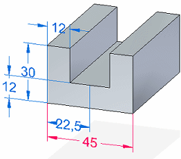
When you use a sketch to construct a feature, the dimensions placed on the sketch migrate to the appropriate edges on the solid body. These migrated dimensions become three-dimensional, PMI dimensions. See the Help topic, Create a dimensioned part from a sketch.
Annotations placed on a sketch also are copied to the model.
You can place dimensions and annotations directly on model edges at any time using any of the commands on the ribbon. In addition, the tool set on the PMI tab conveniently groups all PMI-related functions together in one place.
Note:
The commands you use to place dimensions and annotations on sketches and on the model are the same. However, dimensions and annotations placed on 2D sketch elements and those placed on 3D model elements behave differently. The differences are most apparent during editing.
In synchronous models, you can use PMI dimensions to modify the model. You control the effect of model changes by choosing whether a dimension on a model edge is locked or unlocked, and by specifying the direction of change.
An unlocked dimension means that when faces connected to the dimensioned edge are modified, the dimension value is allowed to change. The default color of an unlocked dimension is blue.
A locked dimension keeps the dimension value from being changed when a connected face is moved or resized.
A dimension must be locked before a formula or variable rule can be applied to the dimension.
The default display color of a locked dimension is red.
In PathFinder, a locked dimension is easily identified by the lock icon  .
.
Note:
All 2D dimensions that migrate from sketches are locked.
You can edit individual dimensions to lock and unlock them, as needed to modify the model. Use the lock button on the Dimension Value Edit dialog box to change a dimension from unlocked to locked.

If the Lock button is not available, select the Maintain Relationships command.
Note:
It is better to leave dimensions unlocked, only locking values as necessary for a particular edit. When you edit the model, the edit is automatically localized, leaving uninvolved dimensions unchanged.
in synchronous modeling, a PMI dimension must be locked before it can be driven by a formula or be used in a formula. Similarly, you cannot unlock a dimension that is controlled by a formula or is used within the formula of another dimension or variable.
To learn how you can modify a model by editing dimension values, see the Help topic, Editing model dimensions.
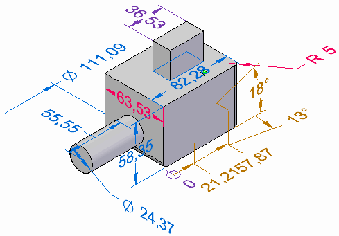
The following table explains the color codes assigned to dimensions.
|
PMI dimension color codes |
|||
|
Color |
Solve condition |
Dynamic Edit? |
Attached to |
|
Blue |
Free |
Yes |
Synchronous elements |
|
Red |
Locked, dimension constrained. |
Yes |
Synchronous elements |
|
Purple |
Driven by other dimension or variable |
No. |
Ordered elements or otherwise uneditable PMI |
|
Brown |
Not available |
No |
Not adequately attached to any element |
As you move the Select cursor over a dimension, it indicates the type of operation that is available if you click at that location:
|
PMI dimension edit cursors |
|||
|
Cursor image |
Operation |
When is it displayed? |
Example |
|
|
Edit the dimension value. |
Cursor is over the dimension text. |
|
|
|
Drag a terminator inside or outside the extension lines. |
Cursor is over a dimension terminator. |
|
|
|
Modify the dimension properties. |
Cursor is over a dimension line or extension line. |
|
There are two types of dimension modification handles: a value edit handle and formatting handles.
A PMI dimension value edit handle is displayed when you click the dimension text. The dimension value edit handle consists of a Dimension Value Edit dialog box (1) and 3D arrow and sphere terminators (2).

The dialog box is where you enter or edit the value.
You control the direction in which the edit is applied by clicking the arrow buttons on the dialog box or by clicking either of the 3D terminators.
The 3D sphere terminator indicates the stationary side.
The default direction is indicated by the highlighted arrow button on the dialog box and by the 3D arrow terminator. A dimensional edit equal in both directions is indicated by the highlighted symmetric button and both 3D arrow terminators.
Sometimes the 3D terminators are more explicit, as shown in the following example.

To learn how to use the dimension value edit handle, see the Help topic, Resize the model by editing PMI dimension values.
If the Dimension Value Edit dialog box is completely disabled, it means the dimension cannot be edited in its current state.

You can change the dimension format using these handles:
The Edit Definition command bar and dimension formatting handles are displayed when you click a dimension line or extension line.
You can use the options on the Edit Definition command bar to modify the dimension properties, including tolerance, prefix, and orientation.
The filled circles are format handles you can drag to change the length of the dimension line and extension lines.

When you click a dimension terminator, such as an arrow, you can drag it outside or inside the extension lines.
To learn how you can show and hide, edit, and manipulate PMI elements, see the Help topic, Display and edit PMI elements.
You can override the value of a driven dimension by right-clicking on the dimension and selecting Not to Scale from the context menu. Solid Edge underlines the values of not-to-scale dimensions.
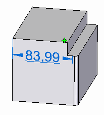
The not-to-scale designation appears in the dimension value edit dialog box.

When you place your cursor on a dimension value, you see two preselection preview features that show you how a dimension value edit will be applied: direction of edit and model face selection.
Where you place your cursor prior to selecting the dimension text influences the direction in which the edit will be applied.
If you place the cursor on the left side of the dimension value, in this example the number 4, then the direction arrow points left. If you select the dimension value by clicking here, the edit will be applied in this direction.
If you place the cursor on the right side of the dimension value, in this example the number 5, then the direction arrow will point right. If you select the dimension value by clicking here, the edit will be applied in this direction.

You can preview what model faces will be affected when you edit a dimension value, by pointing to the dimension text without selecting it. The related model faces are highlighted for you to review them.
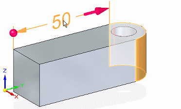
To change the selection set, you can set and clear relationships on the Live Rules options window.
You also can affect the outcome by changing the solve option on the Dimension Edit QuickBar.

To learn more, see these Help topics:
When placing PMI model dimensions that you want to use to change the model, you can use the 3D keypoint filter, Center And Endpoints  and Midpoint
  . This ensures that dimensions are placed on keypoints that are valid for modifying the model. These keypoints are at the centers of circles and arcs and at the midpoints and endpoints of edges.
Note:
The Center and Endpoints, and Midpoint filters use virtual vertices to derive the appropriate keypoint.
To use either of these keypoint filters during dimension placement, select the Keypoints button on the Dimension command bar, under the Other group button. Then select the desired filter.
When you add PMI dimensions and annotations to a model, they are aligned parallel to a dimension plane. The default plane is the base plane most parallel to the screen. However, you can choose a different plane using the Lock Dimension Plane option  on the command bar. This option is available when you have selected a dimension or annotation command.
Only planes you set explicitly appear in the graphics window. These are displayed in red-brown half-highlight.
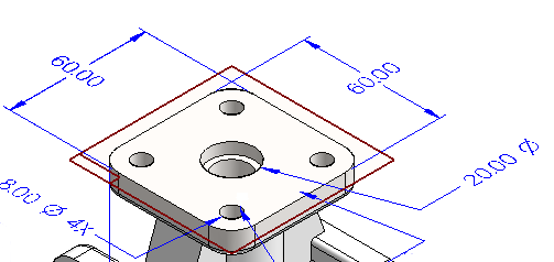
To turn off a dimension plane you have set, press F3.
You can use a model intersection point to place a PMI dimension. Using an intersection point:
Makes it easy to add a dimension to a model edge that has been rounded, split, or trimmed.
Helps the dimension rebind to the original endpoints when the model edge is rounded, split, or trimmed.
Solid Edge automatically detects the presence of intersection points. You can use the intersection point method when placing any dimension.
Note:
To turn off Intersection Point mode, select a dimension command and press the I key.
Example:
Following are some examples of when you might want to place dimensions using intersection points.
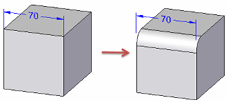
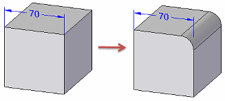
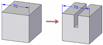
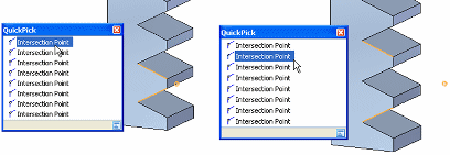
You also can use QuickPick to locate all intersection points—not just the least-distance default—as shown in the following example:
You also can place a dimension using the intersection point of a virtual centerline and the surface of a cylindrical or conical object, including canted, toroid, spherical, and splined shapes. These intersection points are available on demand, without having to invoke Intersection Point mode.
To learn how to use this feature, see the Help topic, Place a PMI dimension using an intersection point.
Sometimes you need to add a PMI element that measures along an axis that is not orthogonal to the object you are dimensioning. This may be the case when you use the Distance Between, Angle Between, Coordinate Dimension, or Symmetric Diameter command.
When one of these dimension commands is in progress, you can use the Dimension Axis option under the Properties group button on the Dimension command bar to set the dimension axis.
You can use the Smart Dimension command to dimension circles, arcs, and ellipses as well as linear elements.
When adding a dimension that requires two points:
The first click determines the point to measure from.
The second click specifies the point or element to measure to.
Dimension stacking and chaining
Linear dimensions can be stacked or chained using the Distance Between command.
Angular dimensions can be stacked or chained using the Angle Between command.
Symmetric diameter dimensions can form a stack, not a chain.
All dimensions in a stack or chain must be placed with respect to the same active dimension plane.
Each stacked or chained dimension has its own entry on PathFinder.

You can place annotations in free space.
You can attach annotations to model faces, surfaces, curves, edges, and sketch elements.
You can attach annotations to existing dimensions and annotations.
Here, the datum annotation is attached to an existing feature control frame.

They also can connect to faces.

You can select and modify individual PMI elements by doing any of the following:
When the dimension format handles are displayed, you can:
Modify PMI dimension round-off, dimension type, tolerance, and prefix for the selected element, using the options on the command bar.
Change the length of the dimension lines and dimension extension lines by selecting and dragging a red dot. You also can select and drag a dimension arrow outside the extension lines.
Use the Properties button on the command bar or the Properties command on the shortcut menu to change formatting properties for font size, terminator type, extension line type, coordinate display, and more.
If you select a dimension, then the Dimension Properties dialog box is displayed.
If you select an annotation, then the annotation-specific dialog box is displayed.
You can make changes that affect all PMI elements at once:
You can make interactive adjustments to PMI text size so it is easier to read when you zoom in and out of the model.
You can change PMI element color globally by modifying the style.
To learn more, see the Help topic, PMI text size and color.
There are several ways you can move PMI elements.
You can move a PMI dimension or annotation using the Move Dimension command. This moves PMI elements in a direction that is normal to the plane where they reside, adding extension lines as needed.
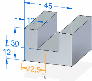
Placing your cursor on a PMI element and then dragging it moves the element within the plane where it resides. The element moves in different ways depending upon what part of the element you drag and whether you use the formatting handles.

You also can use Alt+drag to detach a PMI dimension or annotation from one model element and attach it to a different model element. To learn how, see Reattach or move a dimension or annotation.
If you move an annotation that is attached to another PMI element—including stacked and chained dimensions—they move together.
Moving an annotation connected directly to a face results in translation along the face only, not off it.
To learn how to move and manipulate PMI dimensions and annotations, see the Help topic,Move PMI elements.
You can extract and use property text in PMI dimensions and in callout and balloon annotations.
To use property text in callouts and balloons, select the Property Text button  on the annotation dialog box.
To use property text in a dimension prefix, suffix, subfix, or superfix, copy and paste the property text string into the corresponding text box in the Dimension Prefix dialog box. You can open the Dimension Prefix dialog box by clicking the Prefix button  on the Dimension command bar.
To extract hole information from hole features in a part or assembly, use the Hole Reference, Smart Depth, or Hole callout property text strings.
You can extract bend information—Angle, Radius, and Direction—from a formed part, but not from a flat pattern.
To update property text in PMI elements, use the PMI tab→Property Text group→Update All command.
To convert property text strings to plain text for individual annotations and dimensions, use the Convert Property Text command on the selected element shortcut menu.
To convert all strings in the document, you can use the PMI tab→Property Text group→Convert All command.
To learn more about property text, see the Help topic, Using property text.