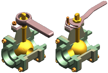
Some products require you to define multiple variations of a single assembly. These variations can be categorized into two types:
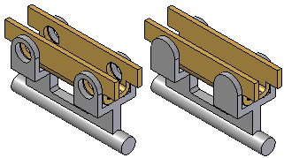
Assembly variations where ALL parts are identical, but some part positions change during the physical operation of the assembly. These types of assemblies contain mechanisms, linkages, actuators, and so forth. In Solid Edge, these types of assemblies are considered Alternate Position Assemblies.
Assembly variations where MOST parts are identical, but some parts and subassemblies are different between the individual assemblies. These types of assemblies may have different components, fastener types, trim, accessories, and so forth. In Solid Edge, these types of assemblies constitute a Family of Assemblies.
The Alternate Assemblies functionality within Solid Edge makes it easier to create and use variations of an assembly because you will have fewer assembly files to manage. Alternate assemblies in Solid Edge include both Alternate Position Assemblies and Family of Assemblies.
Family of Assemblies and Alternate Position Assemblies take advantage of the capability to use the Document Name formula to make the names you display easily identifiable. The name is presented as Formula!<Member Name> to help you differentiate Family of Assemblies or an Alternate Position Assemblies from any other assembly.
Use the Alternate Assemblies tab to create alternate positions for an assembly or a family of assemblies. The first time you click the New Member button on the Alternate Assemblies tab, the Alternate Assemblies Table dialog box is displayed. You must specify whether the assembly will be converted to (A) a family of assemblies or (B) an assembly containing alternate positions. Once the assembly has been converted, it cannot be changed from (A) to (B) or from (B) to (A).
Note:
Ensure that an archive copy of the assembly you are converting exists. You can use the Save As command to create a new working copy of the assembly document before converting it to an alternate assembly.
After you specify the alternate assembly type, you define the names for the first two members. When you click OK, the second member is made the active member on the Alternate Assemblies tab. You can then proceed to define the individual member characteristics.
The Alternate Assembly Edit Table dialog box, available when you click the Edit Table button on the Alternate Assembly tab performs many of the same functions as the Alternate Assembly tab. Additionally, the Alternate Assembly Edit Table dialog box also allows you to view the member characteristics of all the alternate assembly members simultaneously, which you cannot do using the Alternate Assemblies tab. For example, you can see which parts are excluded for all members simultaneously.
The buttons along the top of the Alternate Assembly Edit Table dialog box allow you to perform common functions such as creating new members, deleting members, activating a member, saving a member as a new assembly document, and so forth. You can also print the table to a printer you specify and copy and paste data from the Alternate Assembly Edit Table dialog box to a spreadsheet.
A Preview window is also available with the Alternate Assembly Edit Table dialog box. The Preview window displays the currently selected member.
Some functionality that is available on the Alternate Assembly tab is not available with the Alternate Assembly Edit Table dialog box. For example, you can only exclude relationships using the Alternate Assembly tab.
After defining the first two members of an alternate assembly, you can work with the alternate assembly using the Alternate Assemblies tab or you can click the Edit Table button on the Alternate Assemblies tab to display the Alternate Assemblies Edit Table dialog box, which is a table-driven user interface for working with alternate assemblies that performs similar to a spreadsheet application.
Note:
When you convert an assembly to an alternate assembly, functionality in other areas of the Solid Edge product may be restricted for the alternate assembly. For more information on possible restrictions, see Alternate Assemblies Impact on Solid Edge Functionality.
After you have converted an assembly to an alternate assembly, you can add additional members using the New button on the Alternate Assemblies tab or the Alternate Assemblies Edit Table dialog box. The characteristics of the new member are a copy of the currently active member.
You cannot rename an alternate assembly member. If you want to change the name of an existing member, you can make it the active member, then create a new member with the name you want. You can then delete the other member.
Note:
You cannot delete the default member, which is the first member created. It may be helpful to name the first member Default, or something similar so that later you will know that this member cannot be deleted.
As stated earlier, alternate position assemblies require that all parts in the various member assemblies are the same. The only differences you can define between individual members are for assembly variables, such as the offset values for assembly relationships and the numeric value for sketch-based dimensions.
In the Teamcenter managed environment, Solid Edge Embedded Client integrates Alternate Position Assembly members with Teamcenter Arrangements. This enables you to view each arrangement independently in the Teamcenter Rich Client just as you can in Solid Edge. This capability is valuable for design reviews and illustrates designs that have a range of motion. What you see in CAD is what you see in the Teamcenter Rich Client. The Manage page of the Solid Edge Options dialog box contains the Synchronize Alternate Position Assemblies option that enables each Alternate Position Assembly member to be saved as a Teamcenter Arrangement (this option can also be controlled by Solid Edge Administrator). When the option is enabled, the Upload Document dialog box for Alternate Position Assemblies includes the Default Arrangements column that contains an exhaustive list of values. The value displayed is the currently active Solid Edge member. If the option to Synchronize Alternate Position Assemblies is not enabled and you open an assembly that is saved to Teamcenter with arrangements, as the assembly changes, Solid Edge saves the appropriate updates to the associated Teamcenter arrangement. This allows you to control the behavior while also keeping Teamcenter managed content up to date.
Note:
When unmanaged Alternate Position Assemblies are added to Teamcenter using Add to Teamcenter, the default arrangement is the first member. The default can be changed once it is opened in Solid Edge.
Other options available for alternate position assemblies are discussed in more detail in the following sections.
For a family of assemblies, you can define the following types of variations between the individual family members:
Offset values for assembly relationships
Occurrence overrides
Excluded occurrences
Excluded relationships
Excluded assembly features
Excluded frames
Excluded piping routes
Excluded pattern occurrences
Excluded fasteners
When working with alternate assemblies, you can specify whether the modifications you make affect only the active member, or all members. Modifications that affect only the active member are called local modifications, and modifications that affect all members are global modifications.
When you set the Apply Edits To All Members option on the Alternate Assemblies tab, the modifications you make are globally applied to all members.
When you clear the Apply Edits To All Members option on the Alternate Assemblies tab, the modifications you make are locally applied to only the active member.
For example, when the Apply Edits To All members options is cleared, you can delete a part from one member of a family of assemblies, then place a different part for that member.
Note:
Depending on whether you are working with an alternate position assembly or a family of assemblies, some operations may not be available both locally and globally.
Only one member of an alternate assembly can be active. The currently active member is displayed in the Active Member list. You can activate another member by selecting it from the Active Member list on the Alternate Assemblies tab, or you can select the member column on the Alternate Assemblies Edit Table dialog box, then click the Activate Member button.
You can define different values for an assembly variable using the Member Variables option on the Alternate Assemblies tab. The variable can be associated with an assembly relationship or any other assembly variable. For example, you can reposition parts by defining different values for an angle relationship for individual alternate assembly members.
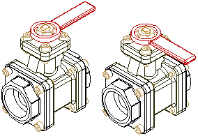
On the Alternate Assemblies tab, set the Member Variables option. Then in the Variable Table, select the variable that you want to add to the Member Variables list. On the Alternate Assemblies tab, click the Add Variables button. The variable is added to all current members. You can then activate a member, and modify the value for the variable. This option is available for both types of alternate assemblies.
You can determine the variable name for an assembly relationship by positioning your cursor over the relationship in the bottom pane of PathFinder. The relationship name is then displayed in the message box on the bottom right side of the Solid Edge window.
Occurrence overrides are defined using the Replace Part command on the Home tab in the Modify group. For example, you may need to define two types of handles for different members. One member has the original handle, and another member has the replacement handle.
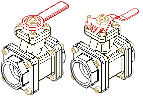
On the Alternate Assemblies tab, activate the member requiring a new handle, then ensure the Apply Edits To All Members option is cleared. You can then use the Replace Part command to replace the original handle part with the new handle part for only the active member.
For alternate position assemblies, this option can only be applied globally, since alternate position assemblies require that all parts are the same for all members. For a family of assemblies, this option can be applied globally or locally.
You can also define occurrence overrides for subassemblies within the active assembly. When replacing subassemblies, the replacement subassembly can also be an alternate assembly. When the replacement subassembly is an alternate assembly, you can select the member you want using the Assembly Member dialog box.
Excluded occurrences are defined by deleting parts for one member, but not others. On the Alternate Assemblies tab, activate the member for which you want to delete a part. Select the part you want to delete in PathFinder, then press Delete. The part is deleted only for the active member, and is added to the Excluded Occurrences list.
For alternate position assemblies, this option can only be applied globally, since alternate position assemblies require that all parts are the same for all members. For a family of assemblies, this option can be applied globally or locally.
Note:
If you are working globally (the Apply Edits To All Members option is set), when you delete a part, the part is physically deleted from the assembly and the part is NOT added to the Excluded Occurrences list.
Excluding relationships for a member allows you to reposition parts using new relationships. For example, you may need to reposition a part for one member by using faces or relationships different from the original member.
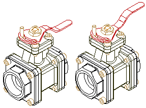
On the Alternate Assemblies tab, activate the member for which you want to delete a relationship. In PathFinder, select the part, then in the bottom pane of PathFinder, select the relationship, and then press Delete. The relationships you delete are added to the Excluded Relationships list. You can then apply new relationships to reposition the part.
When you exclude relationships locally (the Apply Edits To All Members option is cleared), you should also reapply the relationships locally. If you reapply the relationships globally (the Apply Edits To All Members option is set), you can over-constrain the part in other members.
Note:
If you are working globally (the Apply Edits To All Members option is set), when you delete a relationship, the relationship is physically deleted from the assembly and the relationship is NOT added to the Excluded Relationships list.
You can use an assembly feature, but not an assembly-driven part feature in a family of assemblies. For example, you can use the Delete key to exclude a cutout feature on a per member basis while the Apply Edits to All Members option is cleared (you are working locally). The assembly feature is added to the Excluded Assembly Features list for the member.
For more information, see the Alternate Assemblies Impact on Solid Edge Functionality Help topic.
You can use fasteners created with the Fastener Systems command in a family of assemblies. You can delete or place fasteners on a per member basis by clearing the Apply Edits to All Members option first. The Excluded Fasteners option on the Alternate Assembly tab lists excluded fasteners for a family of assembly member.
You can place new patterns of parts, delete an existing pattern of parts, or modify an existing pattern of parts on a per member basis when the Apply Edits To All Members option is cleared.
For example, you can exclude a pattern item in an assembly pattern of parts by deleting the pattern item for one member. On the Alternate Assemblies tab, activate the member for which you want to delete a pattern item. Select the pattern item you want to delete in PathFinder, then press the Delete key. The pattern item is deleted for only the active member, and is added to the Excluded Patterned Occurrences list.
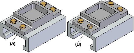
You can drag and drop a new part into the assembly and place it in the empty position in the pattern. This allows you, for example, to delete one pattern item (A) in a pattern of bolts, then use a different bolt (B) in that position.
You can use the Piping Route command to define a piping route (the pipe and fittings) on a per member basis by clearing the Apply Edits to All Members option. You can also create a piping route that applies to all members by setting the Apply Edits to All Members option.
For more information, see the Alternate Assemblies Impact on Solid Edge Functionality Help topic.
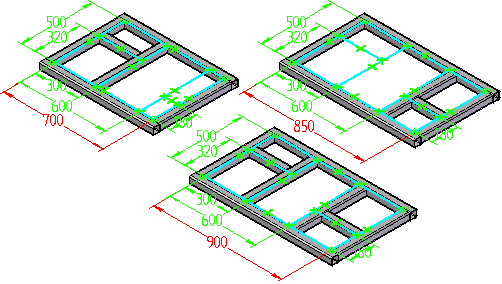
You can use structural frames in a family of assemblies. You can place structural frame components on a per member basis when the Apply Edits to All Members option is cleared. You can also exclude a complete frame component from an individual family of assembly member when the Apply Edits to All Members option is cleared. You cannot exclude individual part documents that make up a frame component. You can also define unique variable values for each family member.
You can also use a member of an alternate components group when defining member characteristics for an alternate assembly that is a family of assemblies, but not an alternate position assembly. For example, you can use the Replace Part command to replace a part in a family of assembly member with an alternate component, rather than use the Exclude Occurrence functionality on the Alternate Assembly tab. Although this approach can be quicker than using the Exclude Occurrence functionality, when you use Revision Manager to copy or move the assembly data set to a new location, any members of the alternate components group that are not used in a family of assembly member will not be included in the data set.
For more information on alternate components, see the Define Alternate Components command Help topic.
You can use adjustable parts in a family of assemblies. You can edit the assembly variable used to control an adjustable part on a per member basis by clearing the Apply Edits to All Members option.
When you place an assembly that has alternate assembly members defined into a higher level assembly, or replace an assembly that is an alternate assembly, the Assembly Member dialog box automatically displays so you can select the alternate assembly member you want.
You can also click the Dynamic Configuration option to display the Dynamic Configuration dialog box, which displays the structure of the alternate assembly master document in a table format and lists the existing members.
You can use the Dynamic Configuration dialog box to do the following:
Review the configuration of existing alternate assembly members.
Define configuration criteria to determine if it matches any existing alternate assembly members.
Define configuration criteria for a new alternate assembly member that you create dynamically.
Define configuration criteria for a new assembly document that you create dynamically.
For example, you can set the Exclude option in the Select List column to specify that a particular part is excluded from the alternate assembly Master document list. If any existing alternate assembly members also exclude that part, the Members Matching Configuration list is updated to include only those members that exclude the part.
If no existing members also exclude the part you specified, you can set the Create New Member or Create New Assembly Document options to create a new alternate assembly member or a new assembly document. When you set the Create New Member option, you can type the new member name in the Dynamic Configuration dialog box. When you set the Create New Assembly Document option and click OK, you can type the new assembly document name in the Save As dialog box.
You can only search and configure a new assembly document or a new family of assembly member for regular assembly components. You cannot search and configure using Family of Assembly-aware features (Assembly Features, Piping, Structural Frames, Patterns, & Fastener Systems).
When you create a new assembly document or a new member that contains Family of Assembly-aware features, a message is displayed to indicate that Family of Assembly-aware features are being included and that you should edit the new document or new member to ensure that the configuration meets your requirements.
When creating a new assembly document, all Family of Assembly-aware features will be copied to the new assembly, except features that are excluded from all members. Family of Assembly-aware features that are excluded from all members will be deleted from the new assembly. You can edit the assembly and delete or suppress Family of Assembly-aware features that you do not want in the new assembly.
When creating a new family of assembly member, all Family of Assembly-aware features will be copied to the new assembly, except features that are excluded from all members. Family of Assembly-aware features that are excluded from all members will be deleted from the new assembly. You can edit the assembly and delete or suppress Family of Assembly-aware features that you do not want in the new assembly.
You can use the Save Member As button on the Alternate Assemblies tab to save the active member as a separate assembly document. The Save Member dialog box allows you to specify a document name and location for the new assembly document. The new assembly document is a regular assembly document.
When an assembly has been converted to a family of assemblies, you can use the Property Manager command to define properties for the parts and subassemblies for individual family members. For example, you can define a document number, revision number, and project name for individual members. These properties are used when you create a parts list for the family member in the Draft environment or an assembly report.
When you change the display of a part in an alternate assembly member, the change only affects the active member, regardless of whether the Apply Edits To All Members option is set or cleared. For example, if you hide a part in one member, the same part in other members will remain displayed, even if the Apply Edits To All Members option is set.