 Hole command (ordered environment)
 Hole command (ordered environment)
Constructs one or more holes in the ordered environment. You can use the Hole command to construct simple, threaded, tapered, counterbored, and countersunk holes.
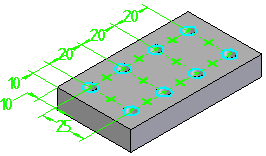
When you select the Hole command, the command bar guides you through the following steps:
| Step 1. |
Plane Step--Define the profile plane. |
| Step 2. |
Hole Step--Define hole parameters and position one or more hole circles. |
| Step 3. |
Extent Step--Define the extent or depth of the holes. |
| Step 4. |
Finish Step--Process the input and create the feature. |
The Type option on the Hole Options dialog box allows you to define the type of hole you want. Solid Edge allows you to construct several types of holes:
(A) simple holes
(B) threaded holes
(C) tapered holes
(D) counterbore holes
(E) countersink holes
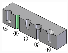
You can only define one type of hole for a single hole feature. To construct a different type of hole, you must construct another hole feature.
The options available on the Hole Options dialog box change, depending on the type of hole you specify. For example, when you set the Threaded option, new options are displayed, which allow to specify the thread type you want.
You can specify a straight thread, a standard pipe thread, or a tapered pipe thread when you set the Type option to Threaded. You can also specify standard or straight pipe threads when you set the Type option to Counterbore or Countersink.
For threaded holes, the size of the hole in the solid model matches the minor thread diameter listed in the Holes.txt file or PipeThreads.txt file for the thread size you selected. For example, when you construct a M24 x 1 metric threaded hole, the hole diameter in the solid model will be 22.917 millimeters, as this is the minor thread diameter listed for this thread in the Holes.txt file.
A different face style is used to indicate that a hole is threaded. The Color Manager command provides an option to define the Face style for Threaded Cylinders. The default value for the Threaded Cylinder option is the Thread style. With the Thread style, you can also use the Rendering tab on the Format View dialog box to specify whether a photo-realistic texture is applied to threaded features in a shaded view.
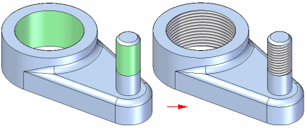
For more information, see the Threaded Features Help topic.
You do not manually draw profiles for hole features. You use the Home tab→Solids group→Hole Circle command and the Hole Options dialog box to define the hole parameters, then position one or more hole circles that Solid Edge draws for you. The hole circle is a graphic representation of the hole parameters, which means that you do not need to add dimensions or relationships that define the hole size. If you place a dimension on the hole circle to define its size, the dimension is placed as a driven dimension.
You can add dimensions and geometric relationships to define the location of the hole circle. If you add a geometric relationship to the hole circle that inadvertently attempts to constrain the size of the hole circle, a message is displayed to warn you that you are trying to over-constrain the profile.
You can place more than one hole circle when constructing hole features. A hole feature with multiple profiles is treated as a user-defined pattern, similar to other pattern features. For example, you can use a user-defined pattern of holes in a part to place an pattern of bolts in an assembly.

Solid Edge allows you to use several extent types when constructing holes:
Through All
Through Next
From/To Extent
Finite Extent
The extents that are available depend on the type of hole you are creating. Simple holes, counterbore holes, countersink holes, and threaded holes support all four extent types. Tapered holes support only the Finite Extent option, but you can define a finite extent length that exceeds the thickness of the part.
With counterbore holes, if you use the Finite Extent option, you define only the hole extent. The counterbore extent is defined by the Counterbore Depth value you specify on the Hole Options dialog box. With the From/To Extent option, the counterbore extends from the profile reference plane to the "From" surface. The hole extends from the profile reference plane to the "To" surface.
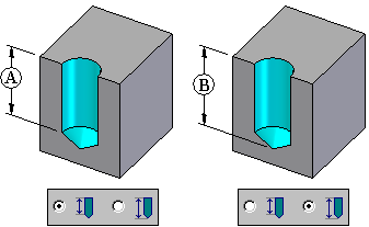
When you construct a hole using the Finite Extent option, you can use the V Bottom Angle option to specify whether the bottom of the hole is flat or V shaped.
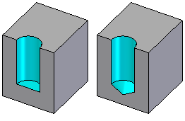
When you set the V Bottom Angle option, you can also type a value for the bottom angle. The angle you specify represents the total included angle. You can also specify how the finite depth value is measured.
You can specify that the depth dimension is applied to the flat portion of the hole where the V bottom angle begins (A), or that the hole depth dimension is applied to the V bottom of the hole (B).
The Holes.txt and PipeThreads.txt files are ASCII text files that are used to populate hole size values on the Hole Options dialog box. You can use a text editor, such as Notepad, to add or edit values in these files. By default, the files are located in the C:\Program Files\Solid Edge ST6\Preferences folder.
You can instruct Solid Edge to look for these files in a different folder, including a folder on another machine on the network. On the File Locations tab on the Options dialog box, select the Hole Size File or Pipe Threads File entry, then click Modify. On the Browse dialog box, specify the drive and folder containing these files. After specifying the location, click Update.
The Saved Settings options on the Hole Options dialog box allows you to save commonly used hole parameters to an external file, named CUSTOM.XML. You can then use the Saved Settings drop list on the Hole Options dialog box or the Hole command bar to select a saved setting later in any Solid Edge document that allows you to construct hole features.
Similar to the Holes.txt file, you can use the File Locations tab on the Options dialog box to specify a folder for the Custom.xml file.
When you specify a machine on the network for the Holes.txt, PipeThreads.txt, and Custom.xml files, all users can use the same parameters for the hole features they construct, which makes it easier to enforce company and industry standards.