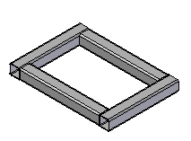
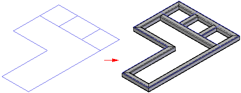
The Frame command, located on the Tools tab, creates structural frames along an existing path consisting of a sketch or assembly sketch. Creating a structural frame consists of:
When you select the Frame command, the Frame Option dialog box is displayed for you to define frame standards, corner treatment, and other options for the structural frame.
The Corner Treatment Options section of the dialog box is where you define corner treatment (end conditions) for the frames.
The corner treatment can be:
Mitered

Butt 1

Butt 2

You can also apply a radius to the adjacent frame components,

extend the end of the frame component,

or apply no end conditions to the adjacent frame components.

The Frame Component Location section of the Frame Options dialog box is where you specify the location of the frame component library. The frame components can be stored in a standard parts library or in a local or network folder.
If the frame components are stored in a folder, you can instruct Solid Edge to look for the components in any folder, including a folder on another machine on the network. You can do this on the File Locations page (Solid Edge Options dialog box). Select the Frame Local Library Folder entry, and modify it to point to the desired location. By default, Solid Edge looks for the frame components in the Solid Edge ST6\Frames folder.
Note:
You can use Solid Edge Administrator to control a user's ability to change the location of the Frame Local Library folder.
The location of the component folders determines the dialog box that is displayed when you select the cross section type and size on the Frame command bar.
If you selected Standard Parts Library on the Frame Options dialog box, the Standard Parts dialog box is displayed for you to select the cross section.
If you selected the Browse for component option on the Frame Options dialog box, the Frame Wizard dialog box is displayed for you to select the cross section from a local or network folder.
After specifying the source for the frame components in the Frame Options dialog box, you select a component cross section on the Frame command bar and select the path segments to define the frame structure. When you select Finish to create the Frame, the frame components are added to the frame structure in the assembly model.
