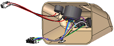
You can use the Wire Harness application to work with assemblies containing electrical conductors.

To activate the Wire Harness application, choose Tools tab→Environs group→Harness.
Solid Edge Wire Harness Design is intended to work with round conductors only and does not support ribbon cables.
Note:
There is no limit on the number of conductors you can use in an assembly.
Generally, there are two design processes used in harness design. In the first design process a 2D electrical schematic is developed first, and the 3D model is derived from the schematic. In the second design process there is no 2D schematic or it is not used in conjunction with the 3D model.
Based on the design process you use, there are two workflows for creating your harness design:
Automatic
Manual
Create a new list either manually or with an ECAD system.
Use the Harness Wizard command to import the net list file to Solid Edge to assign component, connection, and terminal information for the harness design.
Use the Move and Assemble commands to position the automatically placed components if the assembly is not already created.
Bundle and route wires and cables as needed.
Add any wires or cables that were not included in the net list.
Verify all conductors exceed the minimum bend radius and they have the proper slack lengths.
Create manufacturing reports and create a 3D representation of the harness.
Build the assembly to include all required components. You can place the components in the Harness Design environment.
Bundle and route wires and cables as needed.
Verify all conductors exceed the minimum bend radius and they have the proper slack lengths.
Create manufacturing reports and create a 3D representation of the harness.