You can arrange and align new and existing annotations using annotation shapes.
You can create annotation shapes manually using the Annotation Alignment Shape command  .
.
Annotation alignment shapes are also created by the Parts List command. You can choose an alignment shape pattern from the Balloon tab before you place an auto-ballooned parts list on a drawing.
When you select an annotation alignment shape, you can use the options on the Annotation Alignment Shape command bar and in the Alignment Shape Properties dialog box to align annotations.
Once a callout, balloon, or other annotation type is associated with an alignment shape, either by drawing view association or using the Annotations tab in the Alignment Shape Properties dialog box, the shape is highlighted when you select the annotation command to show that it is available and eligible for use.
You can display all of the annotation alignment shapes on the drawing using the Home tab→Annotations group→Show/Hide Annotation Alignment Shape command  .
.
When the spacing assigned to an alignment shape is non-uniform, you can drag an annotation along the shape to adjust the positioning of all other annotations in its path. The minimum spacing value maintains the minimum distance between them. You can change the minimum spacing value on the General tab in the Alignment Shape Properties dialog box.
When the alignment shape has uniform spacing, the first annotation you drag onto it is placed at its center. You can continue dragging annotations onto the shape, and they are arranged uniformly along its length.
You can move all annotations at once by dragging the annotation shape to a new location.
You can disconnect an annotation from an alignment shape by pressing Alt and then selecting the annotation border. You can reattach it by dragging the annotation onto the shape. The other annotations adjust their position accordingly.
When you use the Parts List command to generate item auto-balloons on an assembly drawing view, you can use the alignment shape that was generated by the Parts List command to change the order in which the item balloons are displayed. The following options are available when you select the alignment shape:
You can use the Order option on the Annotation Alignment Shape command bar to rearrange item balloons in a clockwise or counterclockwise manner so that they match the item numbers in a linked parts list.
You can select the Start Balloon option on the command bar and then select a balloon on the drawing to designate the balloon to use as the first balloon in the clockwise or counterclockwise order.
You can select an alignment shape to modify it using the Annotation Alignment Shape command bar or by manipulating the geometry of the shape itself. Associated annotations respond to changes in the shape.
For example, you can:
Move the entire shape by dragging a segment of the shape.
Change the configuration of a multiline shape by dragging a vertex.
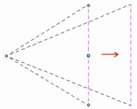
Offset the entire shape by dragging the blue handle in the middle of a segment.

You can use the Shift key to offset just the selected segment.
Add a vertex to a segment using Alt+click. You also can delete a vertex using Alt+click.
Shorten or lengthen a line by dragging its end points. A line also lengthens if necessary to accommodate annotations that are dragged along it.
Delete an alignment shape using the Delete key.
Align annotations using the Annotation Alignment Shape command
Manage annotations that are associated with an alignment shape