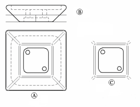
By specifying a drawing view display depth for a back clipping plane, you can simplify any type of drawing view so that geometry behind the plane is removed from the view. This feature can be used, for example, to reduce the visible clutter behind a section view or a broken-out section view.
In this illustration, the hashed line in (A) indicates where the back clipping plane will be applied to the original drawing view display. The orthographic view (B) shows the dynamic line tool used to define the display depth and the location of the back clipping plane. The result (C) shows how the drawing view geometry in front of the plane was trimmed and the geometry completely behind the plane was removed.

A drawing view display depth and clipping plane can be defined for any type of view: orthographic, pictorial, section, auxiliary, and detail views. Dimensions and annotations that are attached to edges removed by the drawing view clipping plane are detached, also.
The Set Drawing View Depth command specifies a visible display depth for the drawing view, and then it applies a back clipping plane. Geometry behind the plane is removed from the drawing view when you update the view.
To adjust the location of the back clipping plane so that more or less geometry is visible, select the Set Drawing View Depth command again and then specify a different depth value.
To remove the drawing view clipping plane and restore the drawing view to its original display depth, use the Remove Defined Depth command from the drawing view's shortcut menu and then update the view.