Synchronous models use face relationships to control the model behavior during an edit. These face relationships include:
Relationships the system finds at the instance of a synchronous edit. These relationships are found if the relationship type is turned on in Live Rules.
User applied relationships that are permanent and are maintained during a synchronous edit.
Locked dimensional relationships.
It is possible that a synchronous edit could fail due to an over constrained condition. It is also possible for a synchronous edit be successful but produce unexpected or unwanted results. Solution Manager provides detail and actions regarding the faces participating in the solution of a synchronous edit. Solution Manager is a tool that graphically interacts with the model to provide control of all relationships relevant to the current solve.
Solution Manager is an optional step during synchronous move or edit operations. When in Solution Manager mode:
Relevant faces change color to represent their role in the solution.
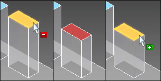
Click on a face that participates in the move to suppress all relations which removes the face from the solution. When you pause over a participating face, a minus symbol appears. Click the face again to unsuppress relations and allow the face to participate. When you pause over a suppressed face, the plus symbol appears.

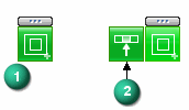
Right-click a face for access to all relationships to the face (1). When hovering over the relationship, a minus symbol appears. When you click the relationship on the palette, that relationship is suppressed for all faces in the solution. If you hover over the relationship, a fly out appears (2). Clicking the fly out only suppresses that face from the solution.

When suppressed, the relationship is greyed out (3). You can repeat the process to add faces back in the solution. When greyed out, hovering over the relationship displays the plus symbol.

Click a locked dimension to relax the constraint. The dimension returns to a locked state after making an edit.

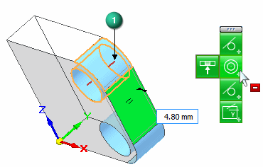
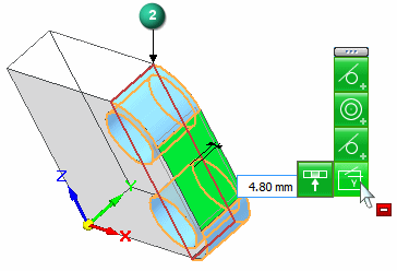
Solution Manager provides graphics to help understand the relationships detected. These graphics appear in a red color. On the found relationship palette, you can hover over a concentric, coplaxis, or symmetry relationship, a concentric axis (1), coplaxis plane (2), or a symmetry plane appears on the model.


You can also hover over a detected relationship on the Live Rules panel and the all concentric axes, coplaxis planes, or symmetry planes appear.
